Resistance Measurement — Common Mistakes
Published by Arun Isaac on
Tags: electronics

Figure 1: Colorful resistors
First of all, the most common mistake is attempting to use the multimeter/ohmmeter to measure the resistance of a circuit element when the circuit element is connected as part of a larger circuit. The resistance reading you get corresponds to not simply the resistance of the circuit element you intended to measure, but rather the equivalent resistance after considering every other circuit element in parallel to it. So, while measuring resistance, one should always disconnect the circuit element of interest from the rest of the circuit and measure the resistance.
One common place where one might make this mistake is when measuring the resistance of potentiometers. One might have adjusted the potentiometer in a circuit and might want to know the new resistance. In such a case, one must not forget to disconnect the potentiometer before attempting to measure its resistance.
And, another common mistake is to measure the resistance with your hands touching the leads of the circuit element. For small resistances, this shouldn’t matter much as your body’s resistance would be too high to affect the reading. But, for higher resistances (in the tens of kohms and above), the resistance of your body will no longer be negligible, and the overall resistance reading will be that of the parallel combination of the circuit element and your body.
In fact, if the resistance of the circuit element is known, one might even use this method to estimate the resistance of one’s body. Also, it is in general not advisable to touch any part of a powered up circuit in operation, especially when it involves high valued resistances. One might inadvertently end up reducing the overall resistance and thus affecting the operation of the circuit.
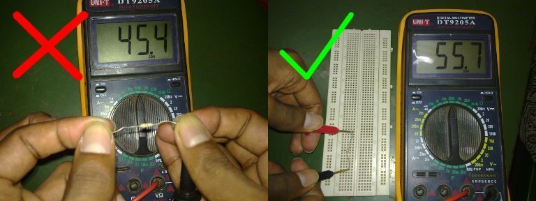
Figure 2: Do Not Touch Resistor Leads!
And, perhaps the final more or less obvious thing would be that you cannot measure the “resistance” of a non-linear element (such as a diode or a transistor). Non-linear elements do not obey Ohm’s law, and there exists no constant value which corresponds to the “resistance” of a non-linear element. Any measure of resistance is obtained as a ratio of the voltage across the element and the current through the element.
Speaking of the “resistance” of non-linear elements, ohmmeters can be used to identify the P and N sides of a diode. When the ohmmeter forward biases the diode, it reads a small value of resistance. When reversed, the ohmmeter reads a large value of resistance, possibly open circuit. Similar techniques can also be used for transistors.
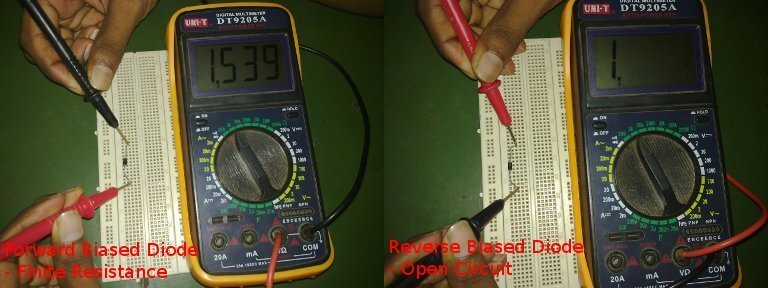
Figure 3: Diode Polarity Check!
Thanks to Prabhu for helping me with the photos!
Image Credits
- Lovely resistors by Windell Oskay, released under the Creative Commons Attribution 2.0 Generic license
 All content is licensed under a