Design of LC Oscillators - Capacitive Overload
Published by Arun Isaac on
Tags: electronics

Figure 1: LC Oscillator Circuit
A lot of people think LC oscillators are little more than resonant LC tanks with amplifiers. The design for most people is nothing more than choosing a value of L and C appropriate for the desired frequency. The resonant frequency of the LC tank is given by the formula
\[ f = \frac{1}{2 \pi \sqrt{LC}} \]
and that’s all there is to the theory. Well, there is also the critical gain of the amplifier necessary to sustain oscillations. But, for a typical LC oscillator, the required critical gain is so low that a situation where your amplifier does not have enough gain is gonna be something of a rarity.
So, armed with the resonant frequency and the critical gain ideas, I went about trying to get LC oscillators working. But, try as I might, I just couldn’t get them to oscillate. I was left forever staring at the straight line DC output on my scope. And thus, for two years (the first and second years of my BE life), I lived with a conscience nagging me about oscillators. I just couldn’t understand why something so elegant refused to work, and that bothered me to no end.
Finally, in the third year of my undergraduate life, when I went back into this whole oscillator business trying to build my own radio circuits, I suddenly saw the solution! Bingo! The L and C of the tank could not be just about any value producing the desired frequency in the formula. If the frequency was high enough, the capacitor in the tank would draw too much current from the output of the amplifier, and the amplifier would overload killing its gain and bringing the whole system down to ashes. Hence, when choosing the capacitor for the tank, one must keep the frequency of operation in mind, and not choose a value of capacitance large enough to short the amplifier.
This simple tweak did everything! It worked flawlessly! This explained all my problems with oscillators. My low frequency oscillators would work fine, but my high frequency ones would just not budge. Now, I understood why! I was being careless with the capacitance values!
Thus, this choice of a proper capacitance value is important for any reasonably high frequency oscillator (Wien bridges, RC phase shifters, quartz, and everything involving capacitors) and not just an LC oscillator. One just cannot afford to overload the amplifier with a carelessly chosen capacitance value.
Here, I have shown a practical LC oscillator circuit with component values. The gain of the amplifier is 10, which is more than sufficient gain for producing sustained oscillations. The two capacitors, each 1 nF, are in series. So, their equivalent capacitance is 0.5 nF. Therefore, the resonant frequency of the tank circuit, as given by the formula is around 225 kHz. At 225 kHz, each of the 1 nF capacitors offer an impedance of around 707 ohms. So, the overall impedance offered by the two capacitors in series would be 1.4 kohms, which is sufficient to not overload the amplifier.
However, if the capacitors were 10 uF each, the overall impedance offered by them at the oscillation frequency would only be 0.28 ohms. Now, that would be quite a cause for concern. The amplifier will most likely overload for such a low value of impedance.
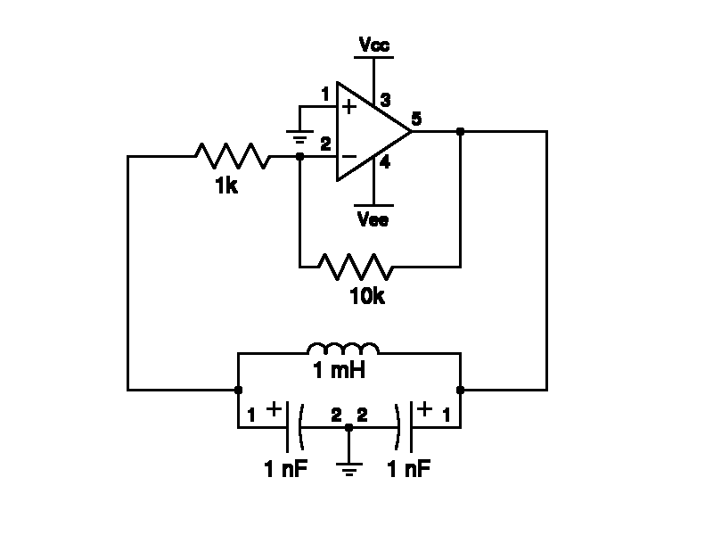
Figure 2: Practical LC oscillator circuit with component values
So, that’s it for now, folks! Hope this helped you somewhere! :-)
 All content is licensed under a